


 Language
< Return

Fonrich Core Products
Fonrich is dedicated to providing corresponding products and solutions for new energy revenue optimization, photovoltaic power station safety, and intelligent O&M management

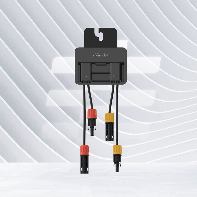
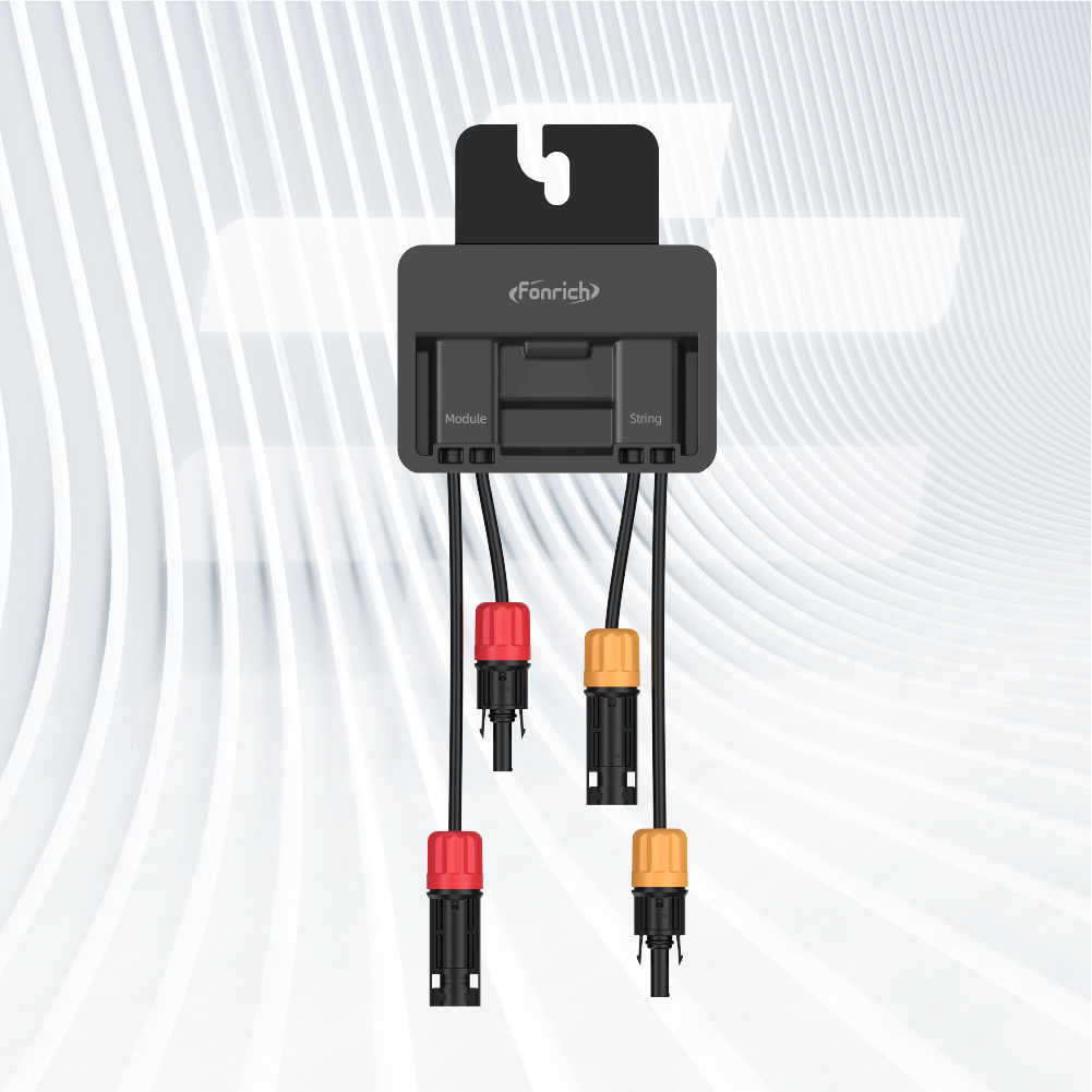
Module-level Rapid Shutdown


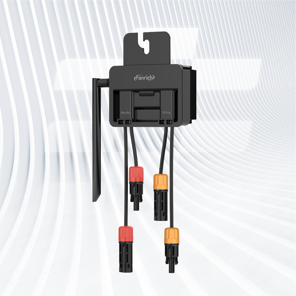
Module-level Optimizer

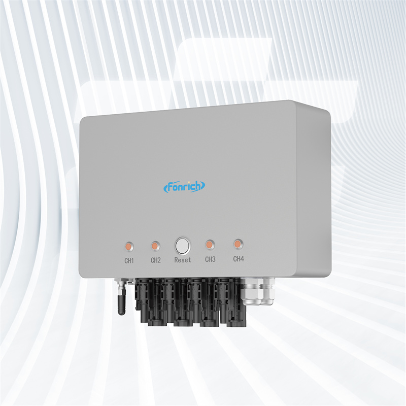
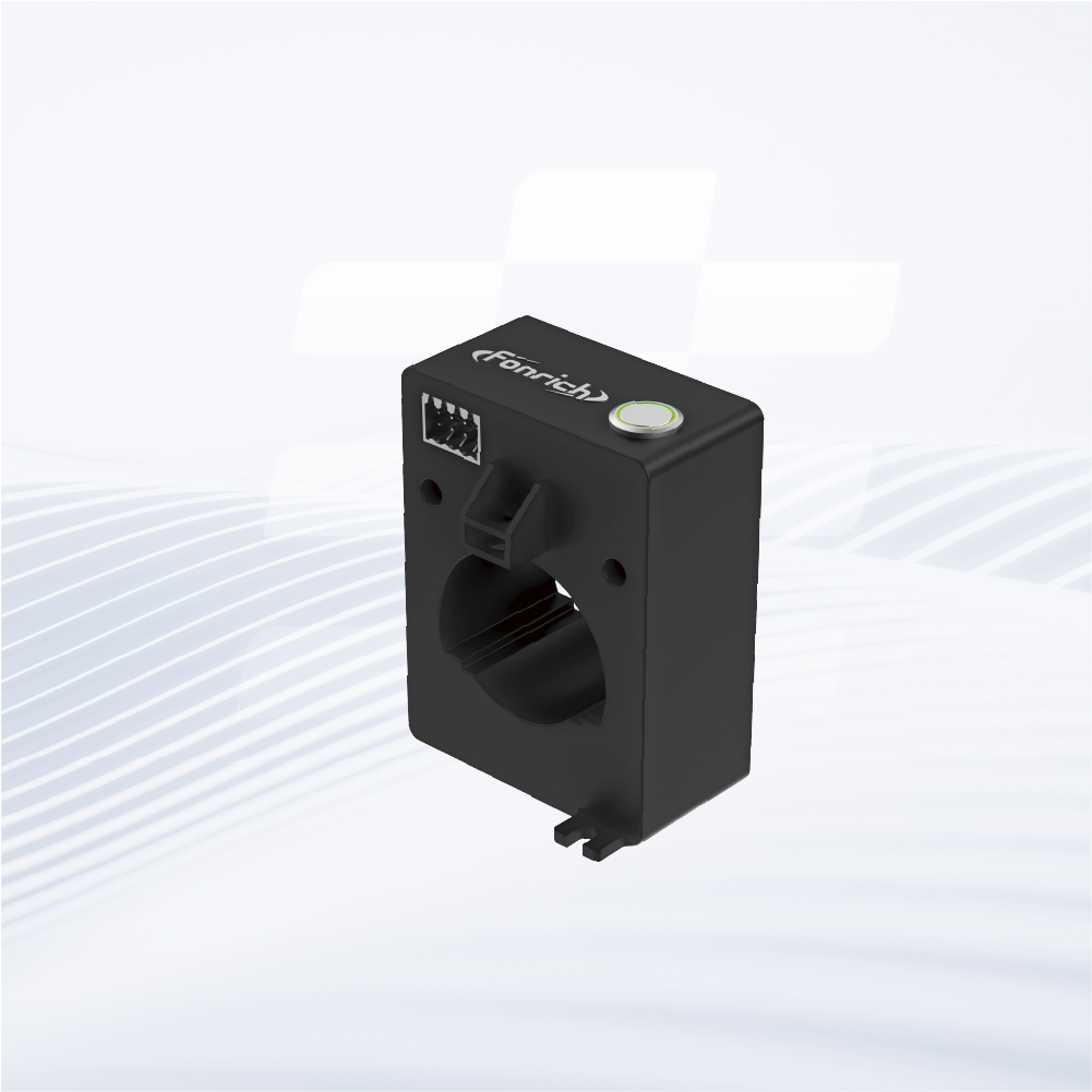
Arc Protection (AFCI)

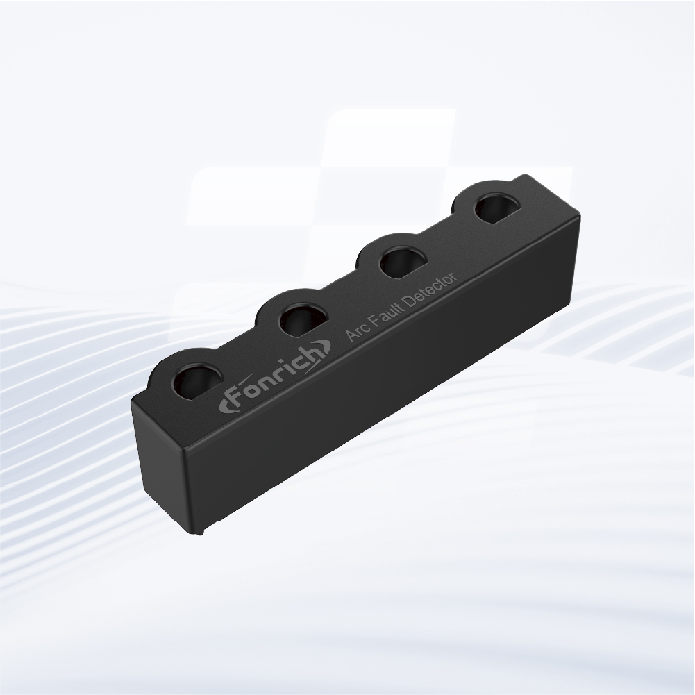
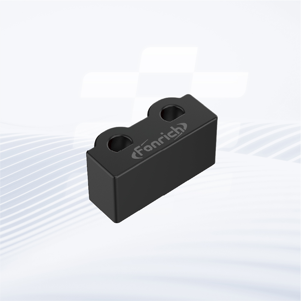
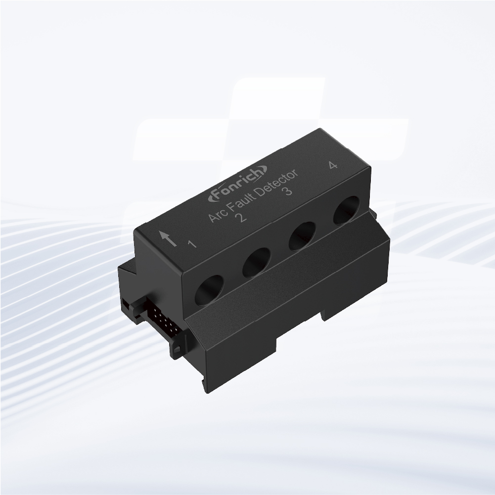
Arc Fault Detector

Other Products

Fonrich Platform
Module-level Rapid Shutdown
Module-level Optimizer
Arc Protection (AFCI)
Arc Fault Detector
Other Products
Fonrich Platform


1st Floor, Building 2, S&T Innovation Building, No. 1588 Lianhang Road, Minhang District, Shanghai
Get industrial insights and Fonrich news here.